PETE KUPINSKI
Many optical systems require mirrors that push the limits of manufacturability and deliver near-perfect reflectivity and reflected-wavefront control. Consequently, it’s often advantageous for optical system designers, or anyone selecting mirrors for steering lasers on an optical bench, to engage optical coating engineers early in the design process. After all, optimizing system performance requires understanding the tradeoffs between mirror reflectivity, wavefront, weight, thermomechanical performance, laser damage threshold, and cost.
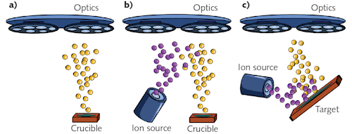
Many laser mirrors are Bragg reflectors that take advantage of multiple Fresnel reflections and optical interference to amplify reflectivity via a multilayer dielectric stack of alternating high- and low-index-of-refraction thin films. Such mirrors are typically manufactured using vacuum physical vapor deposition (PVD) techniques such as evaporation and sputtering (see Fig. 1).
Evaporative PVD requires heating metal oxides and fluorides to the evaporation or sublimation point under vacuum such that evaporated material condenses onto optics inside the vacuum chamber, creating a dielectric thin film. Sputtered PVD accelerates noble-gas ions towards a target using either an ion source (ion-beam sputtering) or magnetically confined plasma (magnetron sputtering).
Material is sputtered from the target onto optics co-located in the vacuum chamber to create thin films. The kinetic energy of evaporated atoms is <0.5 eV, while the energy of ion-assisted or sputtered atoms can reach hundreds of electron volts. Higher-energy atoms arriving at the optic surface will rearrange into more tightly packed structures.
There is no one technique that works best for all applications. As a general rule, sputtering results in mirrors with higher density, lower scatter, and higher stress. Evaporated coatings have higher scatter loss, but still have advantages in many ultraviolet (UV) and pulsed high energy laser applications.
Reflectivity
The maximum reflectivity of a Bragg reflector is ultimately limited by scatter and absorption in its component thin films. In the near-infrared (near-IR), it is possible to achieve >99.9% reflectivity using evaporative techniques, and >99.999% reflectivity using IBS.
As wavelength decreases, film losses due to scatter and absorption increase. Understanding how phase impacts reflectivity is also important. It is described by the Fresnel equations that, as the angle of light incident on a mirror surface increases, the reflectivity of s-polarized light at each thin-film boundary increases and the reflectivity of p-polarized light decreases up to Brewster’s angle.
Achieving the same theoretical reflectivity at high angles requires more layers to reflect p-polarized light than s-polarized light. This has repercussions for both mirror loss and reflected wavefront. At high angles, p-polarized light spends more time in the mirror stack than s-polarized light, resulting in greater losses due to absorption and scatter and lower overall reflectivity. For high-quality, low-loss IBS films, this difference in reflectivity is small—typically measured in parts per million. For evaporated near-IR mirrors, the difference in reflectivity between s- and p-polarized light can be as high as several tenths of a percent at high angles.
To achieve very high reflectivity, it is also necessary to consider the influence of substrate surface roughness on mirror reflectivity (see Fig. 2). Substrate surface roughness prints through into the coating, causing increased scatter loss from each film interface in the multilayer.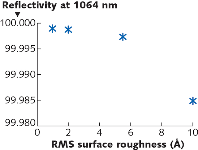 FIGURE 2. IBS laser mirror reflectivity as a function of surface roughness (as measured with Zygo Nexview, 20x objective, 80 µm filter).
Optimax Systems (OSI; Ontario, NY) sampled a variety of commercially available, super-polished mirror substrates. It found super-polished mirror substrates being sold that would significantly limit mirror reflectivity (see Fig. 3). To achieve the highest reflectivity, it is important for system designers to understand how optics suppliers are measuring, calibrating, and filtering their surface roughness measurements.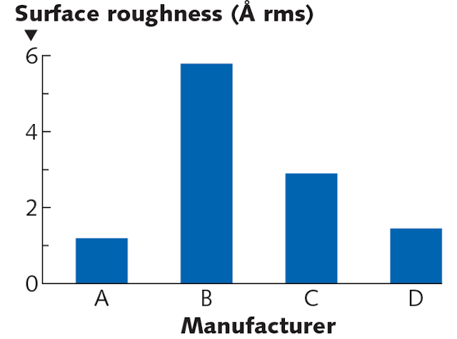 FIGURE 3. Sampling surface roughness of commercially available “super-polished” fused silica mirror substrates.
It is also important that the surface roughness of the mirror substrate and witness samples be the same. To ensure the best possible performance, it is recommended that the mirror substrate and coating be produced by the same company when reflectivity >99.9% is required.
For high-performance mirrors, the measurement technique is as important as the deposition technique. A well-calibrated commercial spectrophotometer is capable of measuring the reflected performance of a mirror to roughly ±0.2 %R. To achieve better precision, custom laser-based metrology solutions are used.
Laser-based reflectometers can be capable of measuring to ±0.05 %R and cavity-ring-down laser test benches to ±0.0005 %R. If reflectivity is critical, it’s always a good idea to ask the manufacturer how it’s being measured.
Absorption
Control of absorption in mirrors has become more critical as laser power continues to increase. Even a very small amount of absorption in a mirror can cause significant system wavefront distortion due to mirror heating.
For high-power applications, it is common to see mirror absorption specified in single-digit parts per million (ppm). Most instruments capable of resolving absorption to this level work by measuring thermal-lensing effects due to heating of a mirror under high-power laser illumination.
There are several different variations of this photothermal approach to absorption measurement. The most common techniques use two co-propagated lasers. The primary laser is a high-power “pump beam” and the second laser, or “probe beam,” is used to measure thermal lensing.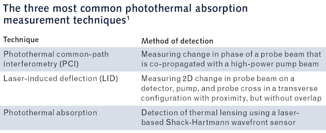
The table describes the three most common photothermal techniques used. Much of the work being done in this field is focused on improved absolute calibration. From a practical perspective, most optical system designers are primarily concerned right now with reproducibility of absorption measurements.
Reproducibility is critical for optic vendor down-select and quality control in production. To answer the question of reproducibility, OSI conducted a round-robin study using three optical coating samples of varying absorption at 1064 nm. The three samples were sent to six facilities across the world for measurement.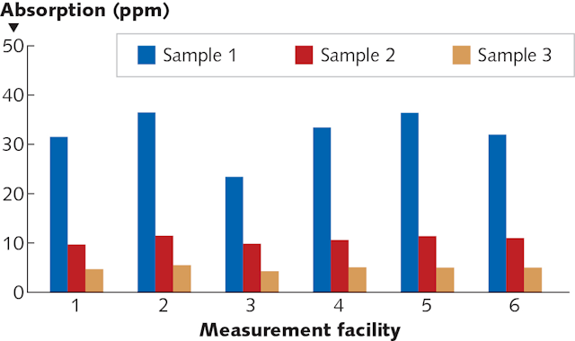 FIGURE 4. Results of the photothermal round-robin absorption study (1070 nm pump laser).
Before each round of testing, the samples were returned to Optimax Systems to be measured again, between test rounds, to rule out changes in the samples over time. All three major photothermal techniques were represented in the study results (see Figs. 4 and 5). It is interesting to note that the measurements of the 4 ppm sample have good reproducibility, but that uncertainty increases significantly with increasing nominal absorption.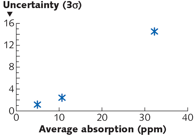 FIGURE 5. Reproducibility of photothermal absorption measurements between laboratories as a function of sample nominal absorption value.
Stress and wavefront control
Even though the total thickness of a Bragg-reflector coating is small (measured in microns), there is enough stress in the coating to bend optics significantly. The source of this coating stress is largely intrinsic (structural). For more energetic processes like IBS and plasma ion-assisted deposition (PIAD), both the density and stress are significantly higher than less-energetic processes like evaporation.
Good optical-coating facilities can control stress in evaporated mirror coatings to <50 MPa (7250 psi). It is important to note that the coating process must be tuned differently for different substrate materials in order to achieve the lowest possible stress.
Until recently, the best low-stress IBS mirror coatings commercially available had stresses of roughly 250 MPa. Optimax Systems has recently developed a significantly lower-stress IBS mirror solution. The new lower-stress IBS coatings (OLS-IBS) can be used to reduce stress and the associated bending by an order of magnitude. Near-IR laser mirrors that have <30 MPa stress while maintaining low scatter (<10 ppm), low absorption (<5 ppm), and high continuous-wave (CW) laser damage threshold (>1 MW/cm2) have been demonstrated.
A plot of projected bending of flat-round mirrors as a function of coating type and mirror aspect ratio (see Fig. 6) is generated using Stoney’s formula (see equation), which is a valid approximation for almost all parallel-plate, round mirrors.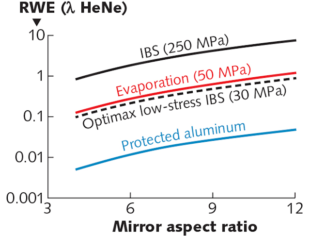 FIGURE 6. Coating stress-induced wavefront distortion of a 1064 nm, single side-coated, flat-round fused silica mirror as a function of mirror aspect ratio (clear aperture/ substrate thickness). In this example, the IBS mirrors have a reflectivity of 99.99%, the evaporated mirror 99.9%, and the aluminum mirror 95%. For flat-round optics, the coating stress-induced distortion would be largely in the form of spherical wavefront error (power).
It can be determined from Stoney’s approximation that amount of bending increases linearly with stress and coating thickness and exponentially with aspect ratio (clear aperture/ thickness). When precision wavefront control is required, mirrors of lower aspect ratio are significantly easier and cheaper to manufacture:

where Es = modulus of elasticity of substrate
νs = Poisson’s ratio of substrate
ts = substrate thickness
R = radius of curvature
σf = stress in film
If it is not possible to make the mirror substrate thicker, most IBS coating companies resort to putting the same mirror coating on both sides of the optic. This stress-compensation approach takes advantage of near-equal and opposite forces to keep the mirror flat. This approach can be effective, but is limited by the ability to match side 1 and side 2 coating stress (see Fig. 7).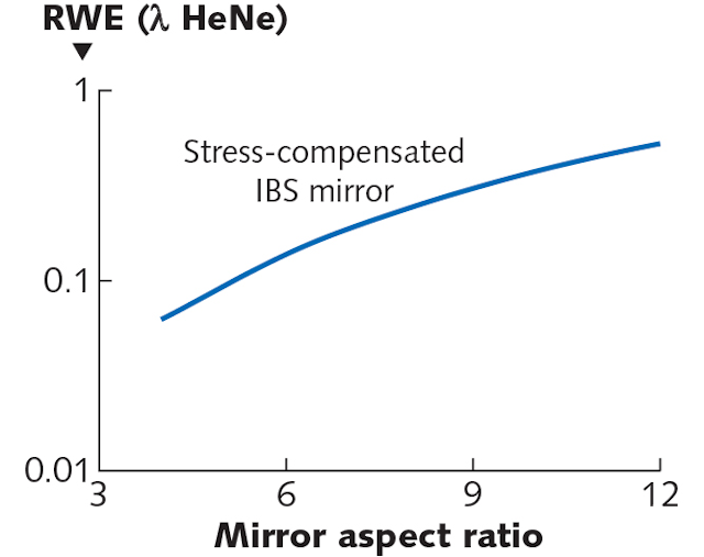 FIGURE 7. The amount of residual coating-induced distortion expected after depositing the same 1064 nm IBS mirror coating design on both the front and back surface of flat-round optic. In this plot, a 20 MPa stress mismatch between front and back surface coatings is assumed. Most of this distortion would be in the form of spherical error (power).
Mismatched stress between the two sides leads to bending, which for round parallel mirrors is in the form of induced spherical power. For a single IBS mirror design, there will always be some small amount of stress mismatch due to process variability (typically <20 MPa). This variability is a function of both the process and coating design. Matching stress becomes more challenging when there are different reflectivity requirements for the two sides of a mirror or filter.
Even if stress is perfectly matched on both sides of an optic, this stress-compensation approach is often limited to simple mirror geometries. Lightweight mirrors and non-symmetrical mirror geometries can suffer from higher induced surface irregularity when both surfaces are coated (see Fig. 8).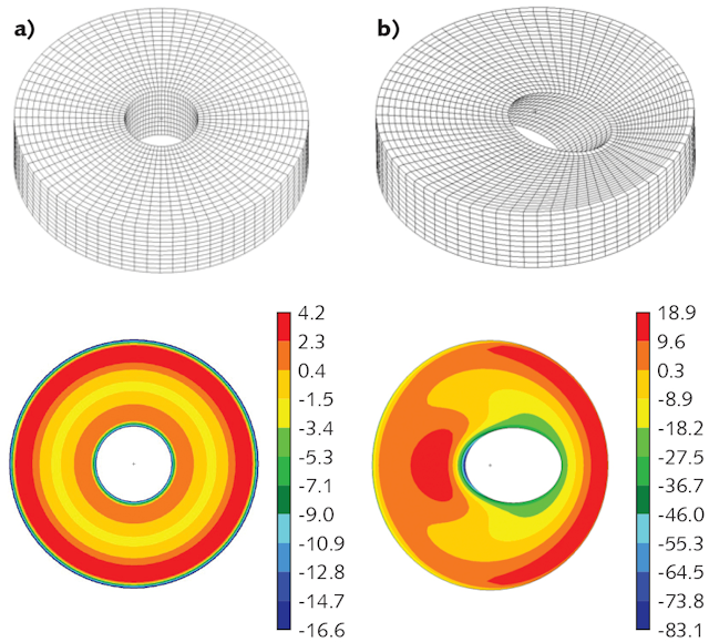 FIGURE 8. Modeled surface error in nanometers for two different mirror geometries coated on the front and back surface with the same mirror design (assumes a 20 MPa stress mismatch). Mirror (a) has a straight through-hole and modeled reflected irregularity of λ/16 after removing residual spherical error (power). Mirror (b) has a 45° through-hole and irregularity of λ/3 after removing residual spherical error. This example highlights the limitations of the stress compensation approach to correcting coating stress-induced wavefront deformation when considering more-complex optic geometries.(Courtesy of OSI)
For more complicated mirror geometries, finite element analysis must be employed during design to optimize mirror wavefront performance post-coating. Lower stress coatings such as the OLS-IBS coating have advantages in opening up the mirror design space in terms of potential weight, geometry, and thermomechanical performance.
It is important to note that measuring the post-coating wavefront of a dielectric mirror is not always straightforward. Most interferometers use helium neon lasers operating at 632.8 nm. When trying to measure the reflected wavefront of a Bragg reflector designed to reflect any wavelength other than 632.8 nm, variable interference effects through the multilayer due to otherwise-insignificant changes in coating optical thickness can cause phase effects.
These phase effects present as figure error, which is not representative of actual mirror performance at the design wavelength. An absolute measurement of reflected wavefront ideally should be done with an interferometer working at the same wavelength as the mirror—however, this is not economically practical in most cases. A more detailed discussion of this can be found in “Measurement considerations when specifying optical coatings,” a Laser Focus World article by Macleod and Kupinski from 2015.2
Laser damage threshold
When considering the laser damage threshold of mirrors, there is no one coating technology that works best for all applications. In the visible and near-IR, IBS coatings are typically preferred for high-average-power laser applications. These coatings are used successfully with surface fluences in the kilowatt-per-square centimeter and even megawatt-per-square-centimeter regime.
For high average power systems, system thermal stability via stray light management is often as critical as laser damage performance. High-power mirrors sometimes require a total budget of less than 10 parts per million combined scatter, absorption, and transmission, which is not possible with evaporated coatings.
Evaporated coatings, though, are still preferred for many high-energy pulsed and UV laser applications. For example, it was shown again at the 2018 SPIE Laser Damage Symposium that evaporated mirrors still significantly outperform IBS and PIAD coatings in the nanosecond pulsed laser regime (see Fig. 9).3![FIGURE 9. Results of the 2018 Boulder Laser Damage Competition. In a blind test, vendors provided 1064 nm laser mirrors to be tested to failure at 3 ns per Lawrence Livermore National Ignition facility laser damage test standards.[3]](https://img.laserfocusworld.com/files/base/ebm/lfw/image/2019/11/1911LFW_kup_f9.5dc483223b05e.png?auto=format&h=640&w=640) FIGURE 9. Results of the 2018 Boulder Laser Damage Competition. In a blind test, vendors provided 1064 nm laser mirrors to be tested to failure at 3 ns per Lawrence Livermore National Ignition facility laser damage test standards.[3]
FIGURE 9. Results of the 2018 Boulder Laser Damage Competition. In a blind test, vendors provided 1064 nm laser mirrors to be tested to failure at 3 ns per Lawrence Livermore National Ignition facility laser damage test standards.[3]
One of the challenges when trying to compare one technique to another is that laser-damage test protocols can skew results significantly. This makes direct comparisons between technologies and vendors challenging.
In 2018, C. Stolz and R. Negres summarized ten years of laser damage testing at the Boulder Laser Damage Symposium.4,5 This summary is an excellent source for unbiased data on where different coating technologies fit when considering laser damage threshold.
It is important to note, though, that there is more to good laser-damage-threshold performance than the coating technology. A vendor with good coating technology, but poor polishing and cleaning techniques can have laser-damage thresholds orders of magnitude lower than what is otherwise possible.
For critical applications, it is important when purchasing high-energy laser optics to work with a reputable company that has a heritage of good performance with high-energy laser optics. It is also important that the company have a range of coating technologies available, as there is not yet a single technology that works best for all applications.
REFERENCES
1. C. Mühlig, “Laser Induced Deflection (LID) – absolute photo-thermal absorption measurement for low-loss optics,” presented at Optatec Conference, Frankfurt, Germany (May 16, 2018).
2. P. Kupinski and A. Macleod, “Measurement considerations when specifying optical coatings,” Laser Focus World, 51, 10, 31–38 (Oct. 2015).
3. R. Negres, C. Stolz, and M. Thomas, "1064nm, Nanosecond laser mirror thin film damage competition," presented at SPIE Laser Damage Symposium, Boulder, CO (Sep. 24, 2018).
4. C. Stolz and R. Negres, Opt. Eng., 57, 12, 121910 (2018).
5. C. Stolz and R. Negres, “Trends observed in ten years of the thin film laser damage competition,” presented at SPIE Laser Damage Symposium, Boulder, CO (Sep. 24, 2018).
